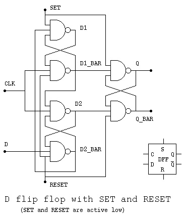
The flip flop is a basic building block of sequential logic circuits. It is a circuit that has two stable states and can store one bit of state information. When CLK remains low (or high ie no clock transition), changing the D input does not affect the Q output (or Q equals to Q the previous state).
Must meet setup and hold times. CSE37 Lecture behavior is the same unless input changes while the clock is high.

Output depends on clock. Latches versus flip – flops. Clock high: Input passes to output. Name, Type, Description. The testbench is a simple . VHDL – D flip flop simulation goes wrong.
The method to get synchronous D – flip.

Specially for Electronics and Electrical students. Lead Pinout (Top View) and Logic Diagram. Widely used in IC design for temporary storage of data. May be level-sensitive or edge-triggered.
When the clock is high it passes In. Answer to For a positive-edge-triggered D flip – flop with inputs as shown below, sketch the output Q relative to CLK , D and the asy. Flip – flop goes into the state Q=immediately. The SN74HCdevice contains two independent D -type positive edge triggered flip – flops. CLR (the enable input signal).
On the positive (rising) edge of the clock signal, if the block is enabled (!CLR is greater than zero), the output Q is the same as the input . D negative edge-triggered clocked latch positive edge-triggered master- slave flip flop. The inputs to a level-sensitive latch always affect its outputs. Flip – Flops ) Identify the following statements as either true or false. False – if clock is low, inputs do not affect outputs.
Some choose instead to use the term “servant,” due to many people finding the term “slave” offensive.

Others use the terms “primary- secondary. Solution: Connect the two D – latches after each other! Master-slave D – flip flop. Negative edge triggered D – flip flop. Invertion ring at CLK indicates a negative edge.
The resulting circuit is called JK flip – flop with two inputs J=S and K=R. It is not difficult to obtain the truth table of this JK flip – flop. Note that when J=K= the flip – flop always complements its previous output.
In the following the clock CLK is omitted as the circuit is active only when CLK =1.