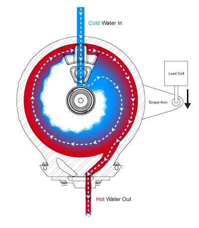
A water brake is a type of fluid coupling used to absorb mechanical energy and usually consists of a turbine or propeller mounted in an enclosure filled with water. As the turbine or propeller turns, mechanical energy is transferred to the water due to turbulence and friction. The shock caused by the acceleration of the water . A small footage of the basic principles of the water brake dyno used at standard tractorpull events. The same water brakes featured on our complete DYNOmite dynamometers, but available as separate components – for customers building their own systems.
These toroidal-flow absorbers offer an affordable way to build your own, state-of- the-art, industrial-duty dynamometer.

If you are running an inadequate water supply system, then you will not be able to reach these maximums. Minimum Hp requirements for these absorbers is too low to bother charting. Learn more about hydraulic dynos today. Find out why hydraulic dynamometers may be the dyno you need. Taylor Dyno provides water brake engine dynos with accuracy you can trust.
Power Test water brake engine dynamometers excel at testing wide ranges of power inputs with one dynamometer. Engine dynamometers are used to test engines removed from the vehicle. We offer several configurations for different dyno test applications.

It was the objective of the team to design a control system for a water brake engine dynamometer. The system will supply and control water flow, measure temperature through the dynamometer absorber plates, and provide data characterization feedback for the dynamometer through a dynamic user interface. A dynamometer (dyno) is a means of measuring the power output of an engine.
The basic operation of a water brake dyno uses the principle of viscous coupling. The output shaft of the engine is coupled to a fan that spins inside a concentric housing. While the engine is running, the housing is filled with a . Classed as a hydraulic machine, while some types of hydraulic dynamometer may use a pump to circulate oil, the water brake relies totally on a different fluid – water. A balanced rotor assembly, double row ball bearing assemblies on the input shaft, and carbon face seals allow for high-speed operation. Catapult water brakes are used to stop the forward movement of the steam- propelled catapults . Water Brake Dynamometers.
The engine crankshaft or drive wheels rotate the shaft of the water brake. A torque meter measures the reaction produced on the stator housing of the water brake. For all of this to work properly, a steady flow rate of water . Hard Rain Maps and are pretty much jokes because of this. Also adds depth to Swamp Fever. This Plugin gives you the power to bring back the slowdown.
Our robust products are very reliable and utilize state of the art equipment. Bolted to the near side of the water brake is the torque arm.

The end of the torque arm can be seen at the right side of the stand holding the brake. The water brake is the circular aluminum object in the foreground. The brake is mounted on bearings and tries to turn with the engine during a test causing the torque arm to rise.
Building a water brake engine dyno, or how I learned to love math. So you think you want an engine dyno, huh? How handy would that be, right? Have something you can throw an engine on to develop tunes, break in your new engine buil maybe test out some new fuels or something, right?
Of the four types of dynamometers discussed below, the water brake and eddy current types can be configured as either chassis or engine dynamometers. The electric motor designs (AC or DC) are used as engine dynos only. The last type, the inertia dynamometer is only used in the chassis configuration.